Current thermal spray studies in the group are focussed largely on plasma spraying (using the installed Plasma Technik P1800 80 kW VPS unit), with particular attention being paid to thermal barrier coatings for gas turbine applications. Recent studies in the group have clarified the mechanisms involved in sintering of zirconia-based top coats under service conditions and the significance of these for the thermo-mechanical stability of the system. Much of this work is being carried out in collaboration with Oerlikon Metco Modelling studies are aimed at prediction of heat transfer characteristics in service and at simulation of the microstructural changes occurring at high temperature.
Current research efforts are focussing on the effects of CMAS (in the form of volcanic ash) on the performance of TBCs. The programme will involve several industrial partners. AMT make small gas turbine engines and have an interest in factors affecting the adhesion of ingested particles onto rotor and stator blades. Monitor Coatings is a UK firm with a globally leading position in high temperature coating technology and extensive expertise in plasma spraying (including process variants such as solution plasma spraying). Two Indian organisations are also involved – BHEL (a major Indian land-based gas turbine company) and the Gas Turbine Research Establishment (an aero-engine development agency).
Facilities at Cambridge include a Vacuum Plasma Spray (VPS) unit, a Particle Size Analyser (PSA), mercury porosimetry, BET surface area analysis, dynamic and static rigs for measurement of elastic constants, an interferometric surface profilometer, a Raman spectrometer, a nanoindenter in a vacuum chamber (with high temperature capability) and a furnace with a computer-controlled periodic quenching capability. A small jet engine is also available, for study of particle adhesion. Details are available at www.msm.cam.ac.uk/mmc/index.php/equipment/equipment-index. Activities at Cranfield will largely focus on modelling of particle impact during plasma spraying. The team at Cranfield is exceptionally well-resourced in terms of both computing hardware and code/algorithms for the development of novel capabilities and model predictions in this area.
A wide range of relevant facilities is available at ARCI, including solution precursor plasma spraying (SPPS), with a provision to spray solution precursors alone or along with a conventional spray-grade powder, either sequentially or simultaneously, a 6 kW diode laser, a vacuum/inert atmosphere furnace, an automated thermal cycling furnace capable of reaching 1200˚C temperature etc. These facilities are complemented by a wide array of characterization tools, including FIB, TEM, EBSD, FE-SEM, SAXS, nanoindentation, erosion testing, laser flash thermal diffusivity, TG-DTA analyzer etc, along with many other materials testing facilities, as described at www.arci.res.in/cmmc/facilities.html.
Proposed work includes development of a novel type of overlay coating, designed to react with ingested CMAS particulate so as to reduce the likelihood of damage. The recently-developed technique of solution precursor plasma spraying (SPPS) will be employed, with the objective of creating fine dispersions of nanoparticles and nanopores offering resistance to (solid state) sintering. A further innovation will be use of alumina substrates, allowing samples to be exposed isothermally to high temperature, so that sintering is homogeneous and there are no changes in interfacial structure. Finally, an instrumented gas turbine will be used to study the deposition efficiency of various types of particulate onto turbine blades, after ingestion into the air intake. The effects of particle chemistry (and hence melting point), particle size, blade surface roughness and engine speed will all be investigated. This will be the first investigation of deposition efficiency under conditions closely representative of those in aeroengines.
1 Background
Gas turbines are of prime importance in a range of industrial sectors, particularly for power generation and for propulsion of aircraft and marine craft. Ceramic coatings within such turbines represent the predominant area of their development, playing increasingly key roles in providing protection against over-heating and oxidation of metallic components. The main material in industrial use is yttria-stabilised zirconia (YSZ), offering chemical stability, low thermal conductivity and relatively high thermal expansivity (reducing coating-substrate thermal misfit strains during heating and cooling). Plasma spraying is widely used to produce such coatings, particularly for power plant turbines. There is a strong driver for expanding their usage in aeroengines, in which PVD coatings are often preferred (in view of their superior resistance to spallation), despite them offering less efficient thermal insulation and being more expensive to produce. Furthermore, improvements in the performance of thermal barrier coatings (TBCs) are required to allow higher turbine entry temperatures and associated gains in engine efficiency.
A key concern for both power plants and aeroengines is with deleterious effects of ingested species, which can adhere to coatings and damage them. Much ingested particulate is often referred to as “CMAS” (Calcia-Magnesia-Alumina-Silica). These are the main ingredients of what might be regarded as a family of ceramic particulate matter. There has, of course, been concern about ingestion of volcanic ash (VA) into aeroengines, and indeed the composition of VA is often such as to be likely to promote severe degradation of ceramic coatings. Other species of concern include salt, particularly in marine environments, and sulphur, often originating in the fuel. The degradation that these species induce can affect both unprotected metallic alloys and ceramic coatings. It is known [1-17] that CMAS ingestion can damage such ceramic layers, particularly TBCs, mainly by promoting sintering and hence making them prone to spallation. Such degradation commonly arises when ingested particulate adheres to the coating and either creates a CMAS-rich outer layer or leads to diffusion into the coating of these oxides, along internal grain boundaries and free surfaces (pores). These oxides do not readily dissolve in the zirconia lattice, but tend to form vitreous phases at grain boundaries, where they accelerate sintering, particularly if significant levels of “liquid” are created. Coatings tend to become more brittle and less strain-tolerant as sintering proceeds, making them more prone to spallation (usually as a result of differential thermal contraction stresses set up during cooling) and also to erosive damage.
Sintering of TBCs, with or without CMAS, leads to microstructural changes that raise the thermal conductivity [6, 18, 19] and the stiffness [3, 5, 20-23], the former caused by growth of the inter-splat contact area [24, 25] and the latter by inter-splat locking and splat stiffening, due to microcrack healing [22]. Coatings become more brittle and less strain-tolerant as sintering proceeds, making them prone to spallation (usually as a result of differential thermal contraction stresses set up during cooling) and also to erosive damage. It may be important to monitor, not only chemical composition (and hence melting point and potency for formation of vitreous grain boundary phases), but also the distributions of particle size and shape. This is likely to affect the “deposition efficiency” (proportion of incident particulate adhering after impact).
Recent investigations in the area have included several [26-34] aimed at exploring modifications to TBC composition and/or microstructure designed to mitigate the effect of degradation caused by CMAS / VA. These studies offer some grounds for optimism that the problem can be controlled, although no clearly effective scientific strategy has emerged so far.
2 Research Programme
2.1 Materials and Specimen Production
Conventional (vacuum) plasma spray (PS) coatings will be produced at Cambridge and ARCI. Solution Precursor Plasma Spray (SPPS) processing will be carried out at ARCI, so as to create nanostructured coatings. SPPS is a flexible thermal spray variant, with a capacity to tailor characteristics of resultant coatings. At ARCI, following substantial efforts to obtain improved understanding of the process [35], the SPPS system (Fig.1) has been modified to allow simultaneous or sequential feeding of solution precursors and conventional spray-grade powders - see Fig.2. Additional possibilities can be explored by incorporating nanoparticle suspensions within the solution precursor. The system can thus be used to deposit, not only a single/bi-layer system, but also multi-layer, graded and composite coatings. The VPS facility at Cambridge has a computer-controlled twin powder feeder, which allows graded coatings to be produced. The prime focus will be on mitigating penetration of CMAS into coatings. Potential strategies will include: (a) addition of solid solution elements to YSZ, to increase the crystallinity of compounds formed on absorption of CMAS, (b) deposition of an active functional layer, such as a pyrochlore, aimed at offering resistance to CMAS penetration and (c) developing a composite coating made up of mixtures of fluorite and pyrochlore structures in different proportions [36, 37].
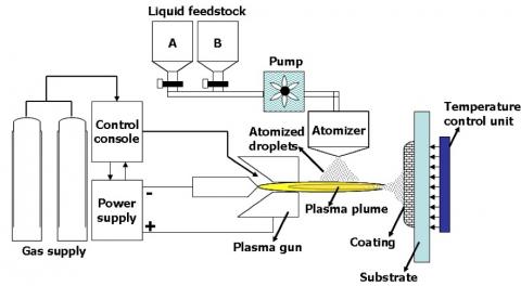
Figure 1: Schematic representation of the SPPS system atARCI
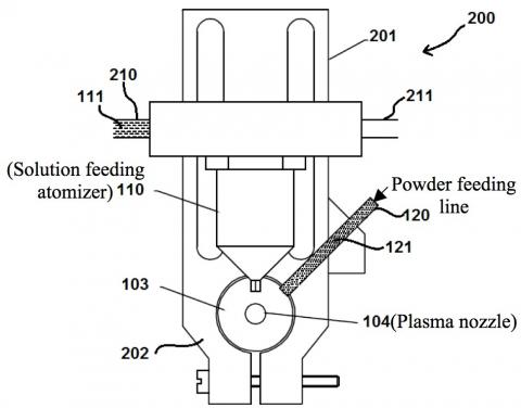
Figure 2: Experimental SPPS set-up at ARCI, allowing simultaneous or sequential feeding of solution precursor/powder
Specimens will be based on “standard” YSZ, although there will also be investigations into novel coating formulations that might offer enhanced resistance to CMAS-induced damage. The “standard” type of (ingested) species will be vermiculite (VM), a natural material representative of a broad class of CMAS material (and similar in melting temperature and amorphous content to many volcanic ashes). The glass transition for VM is typically around 1040˚C, and the melting point is ~ 1360˚C, these values being similar to those for a range of CMAS deposits collected from turbine components [38]. It will be introduced via (a) injection into the air intake of a gas turbine, (b) downstream injection into a plasma gun or (c) by sprinkling of particulate onto a coating and subjecting it to a heat treatment.

Figure 3: Spallation times as a function of thickness for YSZ coatings on Al2O3 substrates heated at 1500oC and quenched at hourly intervals

Figure 4: Spallation times for YSZ coatings (~700-750 microns thick) on Al2O3 substrates, with various VM concentrations, held at 1500oC, and quenched at hourly intervals
Two types of substrate will be employed. Some work will involve Ni-based superalloy substrates, with a standard MCrAlY bond coat, representative of conventional industrial practice. In addition, specimens will be produced by spraying onto alumina substrates. It has already been confirmed that PS coatings can be deposited onto such substrates, provided surfaces have first been roughened (using laser ablation). Isothermal heat treatments will be applied, such that sintering takes place (uniformly throughout the coating), without significant changes being induced within the substrate or at the interface. Samples will be periodically displaced from the furnace and cooled with gas jets, using a computer-controlled set-up, and monitored (via web cams) for coating spallation. The driving force for spallation, from differential thermal contraction between coating and substrate, will be similar to that for YSZ on a Ni superalloy, although the stresses induced in the coating are tensile for an alumina substrate, rather than compressive. The viability of this methodology has already been confirmed and data in Fig.3 show that thicker coatings spall more readily, while Fig.4 illustrates the tendency for spallation to be promoted by VM, via coating stiffness enhancement due to promotion of sintering.
2.2 CMAS Penetration into YSZ Coatings
There is considerable interest in the rate of penetration of CMAS into YSZ coatings, and the influence of pore architecture, CMAS composition, temperature etc. Experiments will be carried out in which VM rich layers are created on the surface of YSZ coatings, followed by various heat treatments. The penetration will be investigated by microstructural examination, including the use of EDX to monitor the composition profiles of species present only in the VM - silicon is the prime candidate for this purpose. Comparisons will be made with model expectations, based on either liquid phase penetration or diffusion along grain boundaries.
2.3 Modelling of CMAS Particle Impact and Adhesion
Models will be developed to simulate impact of CMAS particulate, leading to improved understanding of adhesion mechanisms. The Cranfield group has developed a range of particle/droplet impact models - see Fig.6. For particles solid prior to impact, an existing FEM model [39] will be employed to take account of strain-hardening, thermal softening and heating due to frictional and plastic dissipation. This model will allow study of particle morphology and composition. Attention will be paid to whether particles adhere on impact, with and without transverse motion of the substrate (so that adhesion to both rotors and stators can be modelled). For fully molten particles (droplets), a VOF (volume of fluid) model will be used to track spreading and splashing during impingement, taking account of instability, solidification and air entrapment to model splat formation and bonding [40]. For semi-molten particles, the VOF model will be modified [41]. These models will be used to establish correlations between process parameters and likelihood of adhesion. Parameters include particle size, shape and structure, impact velocity and temperature, angle of incidence, surface topography and mechanical properties of the substrate. Predictions will be compared with the outcome of experimental studies of adhesion in the jet engine.
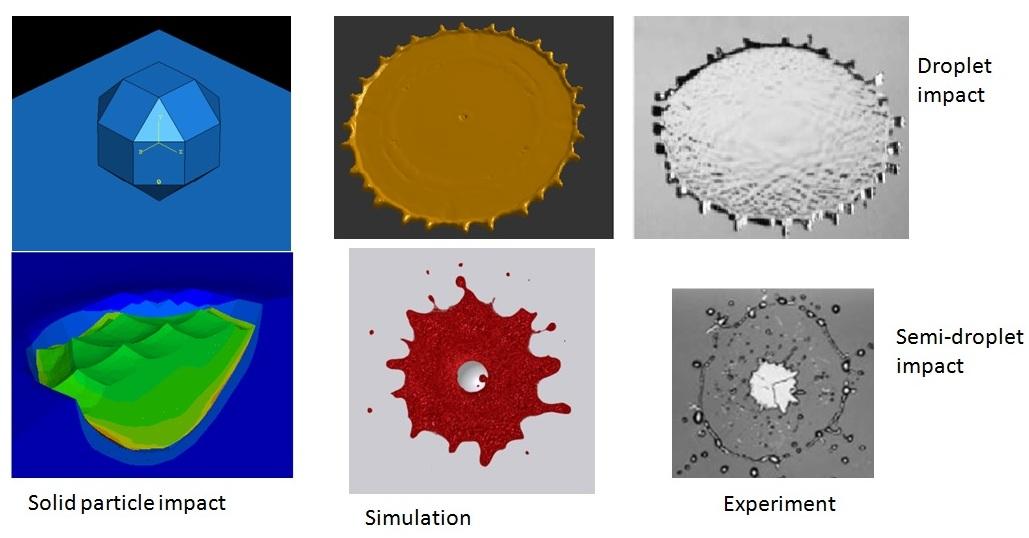
Figure 6: Comparisons between simulated and experimentally observed droplet impact and spreading characteristics, from recent work within the modelling programme at Cranfield.
2.4 Effect of CMAS on Sintering and Spallation
2.4.1 Specimen Production
Coatings will be detached from their substrates, so that they are free-standing (of thickness ~200-500 μm). Particulate will be introduced onto TBC surfaces and held in place by sprayed adhesive. Specimens will then be placed in a furnace at a suitable temperature (~1200-1300˚C) for a short period, allowing CMAS particulate to melt and start to be absorbed (via diffusion) into the TBC surface. Accurate weighing, before and after this operation, will allow the added mass of particulate to be estimated (and also expressed as a proportion of the coating mass). There will be no need to study the effects of particle size or shape, since only the composition and quantity added will be relevant. Sintering heat treatments will then be carried out, at selected temperatures (~1100-1500˚C) and for a series of times (up to ~ 100 hours, although a few 1000 hr. tests will be conducted for the lower temperatures).
2.4.2 Microstructural Development
Development of TBC microstructure will be monitored during particulate absorption and subsequent treatments. This will be done via EDAX composition profiling on transverse sections, and XRD for phase identification, after serial sectioning. Penetration of CMAS in the through-thickness direction will be monitored via the profile of species not present in the YSZ coatings. The XRD spectra will allow estimates of the amorphous content, as a function of depth, as well as indicating whether any new crystalline phases are formed. This could be of practical interest – see §2.6. In addition, Raman spectroscopy will be used to monitor phase transformations, particularly from t’ (tetragonal) to monoclinic.
2.4.3 Stiffness Monitoring
The stiffness (in-plane Young’s modulus) of (detached) coatings is easily measured and gives a sensitive indication of the progression of sintering. It’s also of practical importance, since, for a given misfit strain (from differential thermal contraction between coating and substrate), it determines the (in-plane) stresses created in the coating and hence the magnitude of the strain energy release rate (driving force) for debonding. It will be measured by 4-point bend testing, using a rig incorporating a scanning laser extensometer. These measurements will allow quantification of the acceleration in sintering induced by CMAS, at different concentrations.
2.4.4 Effect of CMAS on Spallation & Erosion Resistance
CMAS will be deposited onto TBC coatings on alumina substrates, as outlined above (§2.4.1). Spallation resistance will be assessed by exposing specimens to high temperature for extended periods, with periodic quenching. The severity of the heat treatment needed to provoke spallation is a measure of this resistance, to be studied as a function of the CMAS “infiltration” level. A fracture mechanics-based methodology to lifing prediction will be adopted, with the strain energy release rate for the cooling being set equal to the interfacial fracture energy. Preliminary data have already indicated that this methodology is viable. Erosion resistance will be studied at ARCI, over a range of temperature.
2.5 Development of CMAS-resistant TBC formulations
In addition to improved understanding of CMAS attack, contributing to the development of guidelines for safe ingestion limits, coating formulations will be sought offering improved protection against such degradation. These could be aimed at reducing the “deposition efficiency” of harmful particulate and/or at countering their deleterious effects after deposition. The former would primarily relate to the free surface topography, while the latter would focus on reducing the effect of CMAS on sintering and hence on resistance to spallation. The most fruitful line is likely to involve species that form (stable) crystalline phases by absorption of elements present in CMAS responsible for the creation of a vitreous (ie liquid or grain boundary) phase - ie Al, Mg, Ca etc. Such a “scavenging” species could be introduced uniformly throughout the coating and/or in a more concentrated form at the outer surface. It’s inappropriate to speculate further on promising types of addition, since this is likely to emerge only after other parts of the programme have been initiated. For example, the studies in §2.4.2 could be useful. Experiments at ARCI will involve heating such layers with a laser. This may generate microstructural changes (eg enhanced crystallinity, larger grain size or coarse layers of porosity), which could improve the efficiency of the layer in terms of CMAS “absorption”.
2.6 Modelling of the SPPS manufacturing process
SPPS is a relatively novel coating technique. Its complexity presents a major challenge for process control. Numerical models will be developed at Cranfield and validated through experimentation at ARCI to facilitate fundamental study of SPPS and create a tool for process control and optimisation. The models will incorporate interactions between solution atomisation and the plasma plume. The solution feedstock comprises droplets containing dissolved components. The in-situ processing of these droplets dictates, not only chemical composition, but also microstructural characteristics of the coating. The critical sub-processes could include atomization of solution feedstock and droplet evaporation, followed by precipitation, nucleation, growth and agglomeration. Depending on droplet size, and consequently heating rate and precipitation during heat-up and vaporization, different particle morphologies will be obtained. The in-flight particle dynamics will be solved using the discrete particle model, with inclusion of possible particle melting and surface transformations. A study will be made of the influence of plasma parameters (i.e. Ar and H2 flow rates, voltage and current) on the physical state of the particles. At the same time, plasma jet fluctuations arising from the axial and rotational motion (for a swirl gas injection) of the arc root along the anode surface [42] will be taken into account.
References
1. Vassen, R, Czech, N, Mallener, W, Stamm, W and Stoever, D, Influence of Impurity Content and Porosity of Plasma-Sprayed Yttria-Stabilized Zirconia Layers on the Sintering Behaviour. Surface & Coatings Technology, 141: (2001) 135-140.
2. Yanar, NM, Stiger, MJ, Maris-Sida, M, Pettit, FS and Meier, GH, The effects of high temperature exposure on the durability of thermal barrier coatings. Key Eng. Mat., 197: (2001) 145-163.
3. Ahrens, M, Lampenscherf, S, Vassen, R and Stover, D, Sintering and creep processes in plasma-sprayed thermal barrier coatings. Journal of Thermal Spray Technology, 13: (2004) 432-442.
4. Lughi, V, Tolpygo, VK and Clarke, DR, Microstructural aspects of the sintering of thermal barrier coatings. Material Science and Engineering, A272: (2004) p. 215-221.
5. Tsipas, SA, Golosnoy, IO, Damani, R and Clyne, TW, The Effect of a High Thermal Gradient on Sintering and Stiffening in the Top Coat of a Thermal Barrier Coating (TBC) System. J. Therm. Spray Technol., 13: (2004) p370-376.
6. Rahaman, MN, Gross, JR, Dutton, RE and Wang, H, Phase stability, sintering, and thermal conductivity of plasma-sprayed ZrO2-Gd2O3 compositions for potential thermal barrier coating applications. Acta Materialia, 54: (2006) 1615-1621.
7. Mercer, C, Faulhaber, S, Evans, AG and Darolia, R, A delamination mechanism for thermal barrier coatings subject to calcium–magnesium–alumino-silicate (CMAS) infiltration Acta Materialia, 53: (2005) 1029-1039.
8. Chen, X, Calcium–magnesium–alumina–silicate (CMAS) delamination mechanisms in EB-PVD thermal barrier coatings Surf. Coat. Techn., 200: (2006) 3418-3427.
9. Strangman, T, Raybould, D, Jameel, A and Baker, W, Damage mechanisms, life prediction, and development of EB-PVD thermal barrier coatings for turbine airfoils. Surf. Coat. Techn., 202: (2007) 658-664.
10. Grant, KM, Kramer, S, Lof, JPAvd and Levi, CG, CMAS degradation of environmental barrier coatings. Surf. Coat. Techn., 202: (2007) 653-657.
11. Paul, S, Cipitria, A, Golosnoy, IO and Clyne, TW, Effects of Impurity Content on the Sintering Characteristics of Plasma Sprayed Zirconia. Journal of Thermal Spray Technology 16: (2007) 798-803.
12. Kramer, S, Faulhaber, S, Chambers, M, Clarke, DR, Levi, CG, Hutchinson, JW and Evans, AG, Mechanisms of cracking and delamination within thick thermal barrier systems in aero-engines subject to calcium-magnesium-alumino-silicate (CMAS) penetration. Materials Science and Engineering A, 490: (2008) 26-35.
13. Li, L, Hitchman, N and Knapp, J, Failure of thermal barrier coatings subjected to CMAS attack. Journal of Thermal Spray Technology, 19: (2010) 148-155.
14. Wellman, R, Whitman, G and Nicholls, J, CMAS corrosion of EB PVD TBCs: Identifying the minimum level to initiate damage. Int. J. Refractory Metals and Hard Materials, 28: (2010) 124-132.
15. Braue, W and Mechnich, P, Recession of an EB-PVDYSZ Coated Turbine Blade by CaSO4 and Fe, Ti-Rich CMAS-Type Deposits. Journal of the American Ceramic Society, 94: (2011) 4483-4489.
16. Wu, J, Guo, H-b, Gao, Y-z and Gong, S-k, Microstructure and thermo-physical properties of yttria stabilized zirconia coatings with CMAS deposits. Journal of the European Ceramic Society, 31: (2011) 1881-1888.
17. Drexler, JM, Ortiz, AL and Padture, NP, Composition effects of thermal barrier coating ceramics on their interaction with molten Ca–Mg–Al–silicate (CMAS) glass. Acta Materialia, 60: (2012) 5437-5447.
18. Zhu, DM and Miller, RA, Thermal Conductivity and Elastic Modulus Evolution of Thermal Barrier Coatings under High Heat Flux Conditions. Journal of Thermal Spray Technology, 9: (2000) 175-180.
19. Renteria, AF and Saruhan, B, Effect of ageing on microstructure changes in EB-PVD manufactured standard PYSZ top coat of thermal barrier coatings. J. Europ. Ceram. Soc., 26: (2006) 2249-2255.
20. Eaton, HE and Novak, RC, Sintering Studies of Plasma Sprayed Zirconia. Surface & Coatings Technology, 32: (1987) 227-236.
21. Siebert, S, Funke, C, Vassen, R and Stover, D, Changes in Porosity and Young's Modulus due to Sintering of Plasma-Sprayed Thermal Barrier Coatings. J. Mater. Proc. Technol., 93: (1999) 217-223.
22. Thompson, JA and Clyne, TW, The Effect of Heat Treatment on the Stiffness of Zirconia Top Coats in Plasma-Sprayed TBCs. Acta Materialia, 49: (2001) 1565-1575.
23. Choi, SR, Zhu, DM and Miller, RA, Effect of sintering on mechanical properties of plasma-sprayed zirconia-based thermal barrier coatings. Journal of the American Ceramic Society, 88: (2005) 2859-2867.
24. McPherson, R, A Model for the Thermal Conductivity of Plasma-Sprayed Ceramic Coatings. Thin Solid Films, 112: (1984) 89-95.
25. Golosnoy, IO, Tsipas, SA and Clyne, TW, An Analytical Model for Simulation of Heat Flow in Plasma Sprayed Thermal Barrier Coatings. J. Ther. Spray Techn., 14: (2005) 205-214.
26. Aygun, A, Vasiliev, AL and Padture, NP, Novel thermal barrier coatings that are resistant to high-temperature attack by glassy deposits. Acta Mater., 55: (2007) 6734-6745.
27. Mohan, P, Yao, B, Patterson, T and Sohn, YH, Electrophoretically deposited alumina as protective overlay for thermal barrier coatings against CMAS degradation. Surface & Coatings Technology, 204: (2009) 797-801.
28. Mohan, P, Patterson, T, Yao, B and Sohn, Y, Degradation of thermal barrier coatings by fuel impurities and CMAS : thermochemical interactions and mitigation approaches. Journal of Thermal Spray Technology, 19: (2010) 156-167.
29. Rai, AK, Bhattacharya, RS, Wolfe, DE and Eden, TJ, CMAS-Resistant Thermal Barrier Coatings (TBC). International Journal of Applied Ceramic Technology, 7: (2010) 662-674.
30. Drexler, JM, Shinoda, K, Ortiz, AL, Li, D, Vasiliev, AL, Gledhill, AD, Sampath, S and Padture, NP, Air-plasma-sprayed thermal barrier coatings that are resistant to high-temperature attack by glassy deposits. Acta Materialia, 58: (2010) 6835-6844.
31. Gledhill, AD, Reddy, KM, Drexler, JM, Shinoda, K, Sampath, S and Padture, NP, Mitigation of damage from molten fly ash to air-plasma-sprayed thermal barrier coatings. Materials Science and Engineering: A, 528: (2011) 7214-7221.
32. Mechnich, P, Braue, W and Schulz, U, High-Temperature Corrosion of EB-PVD Yttria Partially Stabilized Zirconia Thermal Barrier Coatings with an Artificial Volcanic Ash Overlay. Journal of the American Ceramic Society, 94: (2011) 925-931.
33. Drexler, JM, Gledhill, AD, Shinoda, K, Vasiliev, AL, Reddy, KM, Sampath, S and Padture, NP, Jet Engine Coatings for Resisting Volcanic Ash Damage. Advanced Materials, 23: (2011) 2419-2424.
34. Drexler, JM, Chen, C-H, Gledhill, AD, Shinoda, K, Sampath, S and Padture, NP, Plasma sprayed gadolinium zirconate thermal barrier coatings that are resistant to damage by molten Ca–Mg–Al–silicate glass. Surface and Coatings Technology, 206: (2012) p. 3911-3916.
35. Sivakumar, G, Dusane, RO and Joshi, SV, In situ Particle Generation and Splat Formation During Solution Precursor Plasma Spraying of Yttria-Stabilized Zirconia Coatings. J. Amer. Ceram. Soc., 94: (2011) 4191–4199.
36. Aygun, A, Vasiliev, AL, Padture, NP and Ma, X, Novel Thermal Barrier Coatings that are Resistant to High-Temperature Attack by Glassy Deposits. Acta Materialia, 55: (2007) 6734-6745.
37. Kramer, S, Yang, J and Levi, CG, Infiltration-Inhibiting Reaction of Gadolinium Zirconate Thermal Barrier Coatings with CMAS Melts. J. Amer. Ceram. Soc., 91: (2008) 576-583.
38. Smialek, J, Archer, F and Garlick, R, Turbine airfoil degradation in the persian gulf war. JOM Journal of the Minerals, Metals and Materials Society, 46: (1994) 39-41.
39. Gu, S and Kamnis, S, Bonding mechanism from the impact of thermally sprayed solid particles. Metallurgical and Materials Transactions A, 40: ( 2009) 2664-2674.
40. Tabbara, H and Gu, S, Numerical study of semi-molten droplet impingement Applied Physics A: Materials Science & Processing, 104: (2011) 1011–1019.
41. Kamnis, S and Gu, S, Numerical modelling of droplet impingement. Journal of Physics D: Applied Physics, 38: (2005) 3664-3673.
42. Kieschke, RR, Roberts, KA and Clyne, TW, Instabilities in the Vacuum Plasma Spraying Process. Surf. & Coat. Techn., 46: (1991) 25-38.
The deposition of volcanic ash on aeroengine components is also being studied and the following research project is oriented towards determining the criteria for particle sticking.
1. Background
Airborne volcanic ash can be a significant threat to the safe operation of gas turbine powered aircrafts [1]. In recent years, especially during the past 20 years, the threat from volcanic ash to the aviation industry has been recognized and documented [2]. The 2010 eruption of Eyjafjallajokull (Iceland) and the 2011 eruptions of Grimsvotn (Iceland) and Cordon Caulle (Chile) have caused millions of pounds worth of damage to the airline industry worldwide. Overall 95,000 flights had to be cancelled all across Europe during the six days of Eyjafallajokull eruption alone costing the airline industry millions of pounds.
A range of potential damage mechanisms have been identified such as deposition of ash onto hot section components, erosion of compressor airfoils, cooling hole blockage of the high pressure turbine, unwanted changes to the control system, oil system contamination and potential damage to electronic components [1]. Interaction of volcanic ash with surfaces in the jet engine can cause severe malfunction especially at high temperatures as volcanic ash has a relatively low glass transition temperature (Tg ~ 700°C) in comparison to the temperature of the jet engine (1200 - 1400 °). As a consequence, these particles tend to deposit on some engine parts [3]. However, the deposition efficiency depends on the ash characteristics such as size, composition and amorphous/crystalline content. These deposits can cause local overheating and increase levels of surface roughness which produce a corresponding increase in the heat transfer by 30% and surface sheer stress by 300% [3]
2. Research Programme
2.1 Volcanic Ashes
Several volcanic ashes will be characterized and sieved to cover a wide range of particle sizes, composition and amorphous/crystalline content. Figure 1 presents SEM micrographs of some selected volcanic ashes that will be studied coming from different volcano sources such as Laki, Hekla and Eldgja. Moreover, Fig. 1 d shows their corresponding X-Ray diffraction patterns where it can be seen that each of them present different amorphous/crystalline content.
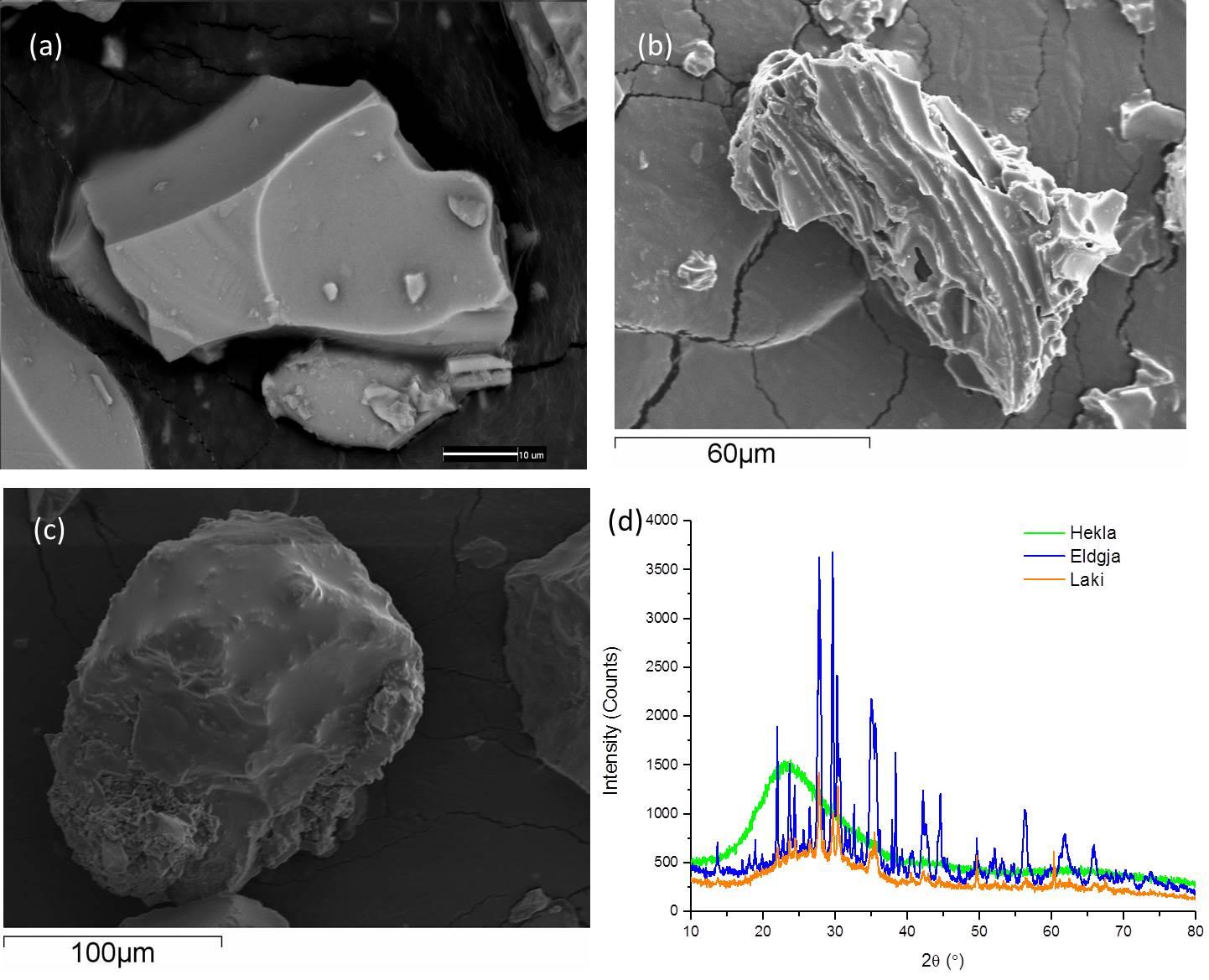
Figure 1: a, b, c) SEM micrograph and d) X-Ray diffraction pattern of several Volcanic Ash
2.2 Development of Ash Particle Deposition Set-Up
A new Set-Up is being developed where ash powder (sieved to different particle size ranges) will be fed at predetermined rates into the Vacuum Plasma Spray (VPS), within a controlled pressure chamber. Gas flow will be confined within a tube, simulating the combustion chamber of a turbine, with gas temperature and velocity being in broadly comparable ranges (T ~ 700-1200˚C, V ~ 300-400 m s-1). Deposition will take place on a static surface (with or without a coating), inclined at selected angles to the axis of the tube - see Fig.2. (Earlier work [5] has shown that deposition takes place predominantly on static components in a turbine.)
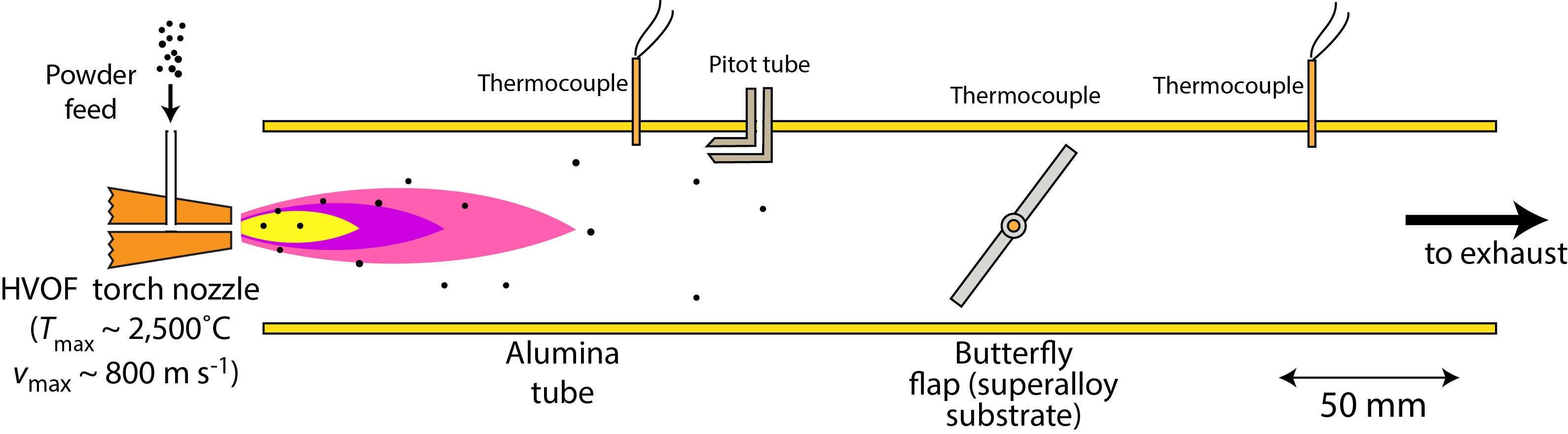
Fig.2: Schematic of Ash Particle Deposition Set-up.
Using this new set-up, information concerning the significance of ash characteristics (particularly phase constitution, and hence softening temperature, as well as particle size distribution) in determining whether deposition is likely for given engine operating conditions will be obtained. Guidelines may involve the specification of a maximum permissible ash burden in ingested air. However, it already seems clear that these are unlikely to be universal. Even the currently recommended (CAA) safe level of 4 mg m-3 would lead to a large aeroengine ingesting several grams of ash per second (although admittedly it would not all go through the turbine). Since even a gram or so (ie ~105 particles of 100 µm diameter) would be likely to cause severe problems in certain locations within the turbine, the key issue clearly concerns the proportion of ingested ash that is likely to be deposited. This in turn is likely to depend on both particle size distribution and the phase constitution of the ash. The deposition will be investigated using a combination of scanning electron microscopy, high precision weighting and particle size measurements.
The numerical modelling activities will be carried out using COMSOL computational fluid dynamics software. The software will be used to simulate the temperature distribution within and trajectory of particles ingested into the gas stream. The simulations will cover both heating and acceleration in flight and impingement possibilities. The velocity normal to the substrate surface at impingement, the particle surface temperature and the substrate surface temperature will be combined with conjunction with experimental data concerning deposition to obtain a criterion for deposition. The assumption will be made that particles do not collide in flight but there is a high likelihood that if there is prior deposition at a specific impact site the deposition may be affected.
2.3 Modelling of CMAS Particle Impact and Adhesion
Models will be developed to simulate impact of CMAS particulate, leading to improved understanding of adhesion mechanisms. The Cranfield group has developed a range of particle/droplet impact models (Fig. 3). For particles solid prior to impact, an existing FEM model [6] will be employed to take account of strain-hardening, thermal softening and heating due to frictional and plastic dissipation. This model will allow study of particle morphology and composition. Attention will be paid to whether particles adhere on impact, with and without transverse motion of the substrate (so that adhesion to both rotors and stators can be modelled). For fully molten particles (droplets), a VOF (volume of fluid) model will be used to track spreading and splashing during impingement, taking account of instability, solidification and air entrapment to model splat formation and bonding [7]. For semi-molten particles, the VOF model will be modified [8]. These models will be used to establish correlations between process parameters and likelihood of adhesion. Parameters include particle size, shape and structure, impact velocity and temperature, angle of incidence, surface topography and mechanical properties of the substrate (coating). Predictions will be compared with the outcome of experimental studies of adhesion in the jet engine. The numerical modelling activities are going to be carried out using COMSOL computational fluid dynamics software to simulate the temperature distribution within and trajectory of particles ingested into the gas stream. The assumption will be made that particles do not collide in flight but there is a high likelihood that if there is prior deposition at a specific impact site the deposition may be affected.
Figure 3: Comparisons between simulated and experimentally observed droplet impact and spreading characteristics, from recent work within the modelling programme at Cranfield.
2.4 Deposition of Volcanic Ash on Turbine Surfaces Inside a Small Jet Engine.
Deposition of volcanic ash has been studied using an AMT Pegasus engine (Fig.4a) with monitoring of turbine speed, exhaust temperature, fuel consumption rate and engine thrust - see www.amtjets.com/PegasusHP.php. While it is clearly a small engine, with a high maximum turbine speed (~120,000 rpm) and gas exhaust velocity, the thermal field (exhaust temperature ~ 700-800˚C) and gas flow conditions are similar to those typical of larger engines. Particulate will be fed into the air intake at a controlled rate. The effect of particle size distribution was investigated using sieved samples. Deposition efficiency has been assessed using a customised optical fibre and imaging (“borescope”) system, allowing internal regions of the turbine assembly to be viewed - see Fig.4b. While deposition efficiencies are routinely studied for thermal spraying operations, this is a novel line of investigation for deposition of ingested particulate within a gas turbine engine, and of interest in a wider context than just that of CMAS ingestion [5].
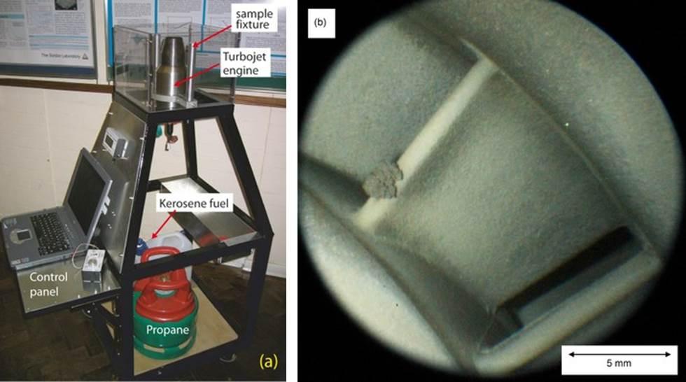
Figure 4: (a) The AMT Pegasus turbojet engine at Cambridge and (b) the borescope image showing adhesion of ingested VA particulate at the leading edge of a stator blade within the AMT engine, after ingestion under a given set of conditions
[1]M. G. Dunn, "Operation of Gas Turbine Engines in an Environment Contaminated with Volcanic Ash," Journal of Turbomachinery, vol. 134, September 2012.
[2] C. G. Levi, J.W Hutchinson, M.H Vidal-Setif, C.A Johnson "Environmental Degradation of Thermal Barrier Coatings by Molten Deposits," MRS Bulletin, pp. 932-941, 2012.
[3] W. Song, K.U ess, D.E Damby, F.B Wadsworth, Y. Lavellee, C. Cimarelli, D.B. Dingwell, "Fusion Characteristics of Volcanic Ash Relevant to Aviaiton Hazards," American Physical Union, 2014.
[4] U. Kueppers, C. Cimarelli, K.U Hess, J. Taddeucci, F.B Wadsworth, D.B Dingwell, "The Thermal Stability of Eyjafjallajokull Ash Versus Turbine Ingestion Test Sands," Journal of Applied Volcanology, vol. 3, 2014.
[5] M. Shinozaki, KA Roberts, B van der Goor & TW Clyne, Deposition of Ingested Volcanic Ash on Surfaces in the Turbine of a Small Jet Engine, Adv. Eng. Mats., 15 (2013) p.986-994.
[6] S. Gu, and S. Kamnis, , Bonding mechanism from the impact of thermally sprayed solid particles. Metallurgical and Materials Transactions A, 40: ( 2009) 2664-2674.
[7] H. Tabbara and S. Gu, Numerical study of semi-molten droplet impingement Applied Physics A: Materials Science & Processing, 104: (2011) 1011–1019.
[8] S. Kamnis and S. Gu Numerical modelling of droplet impingement. Journal of Physics D: Applied Physics, 38: (2005) 3664-3673.