
The Plasma Electrolytic Oxidation (PEO) Process
Plasma Electrolytic Oxide (PEO) Coatings are hard, dense, wear-resistant, and well-adhered oxide coatings for metals such as aluminium and magnesium. The process by which they are grown may also be referred to as micro-arc oxidation (MAO) or spark discharge anodizing. Essentially, it involves the modification of a conventional anodically grown oxide film by the application of an electric field greater than the dielectric breakdown field for the oxide. Discharges occur, and the resulting plasma-chemical reactions contribute to the growth of the coating. More significantly, local conditions of heat and pressure sinter and anneal the coating. Rapid cooling also modifies the oxide, resulting in a complex mixture of amorphous material and nanocrytalline phases.
The process may be applied to any valve metal such as aluminium, magnesium or titanium, and to a wide range of their alloys. Coating properties depend on the substrate alloy, but also on the electrolyte used and on the many parameters of the electrical system. On aluminium, dense alumina coatings (approximately 3% porosity) up to 130 microns thick can be formed, but more porous coatings up to 600 microns in thickness can also be formed by using different electrolytes. Typical alumina coatings consist of a relatively dense polycrystalline layer of alpha-alumina, with a softer, more porous layer of gamma-alumina formed on top.
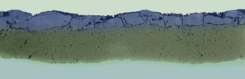

120 micron PEO coating on 7075 aluminium (source: Keronite.com)
The process is currently being developed and marketed in the UK by Keronite™ Ltd. (owners of the registered trade mark Keronite) who are based in Haverhill, near Cambridge. Keronite Ltd are actively involved in research collaborations with the Composites and Coatings Group.
PROPERTIES OF KERONITE™ COATINGS:
- Hardness: typical coatings on aluminium have a hardness of 1400-1700 HV
- Adhesion: the coating is extremely well adhered to the substrate from which it forms
- Heat resistance: the coating can withstand several seconds of 2000 degrees C without undergoing any change.
- Thermal insulation: typical thermal conductivities are of the order of 1 W m-1 K-1, providing good thermal insulation to the substrate material
- Wear resistance: superior to that of coatings produced by hard anodising
- Dimensional tolerance: coatings are uniform and of controllable thickness. After polishing off a poorly adhered 'external layer', typical coatings project from the coated components by approximately 25%.
- Friction: polished Keronite coatings have a low friction coefficient (0.5 measured with respect to itself when dry, 0.1 when lubricated)
- Electrical insulation: operates up to 500 degrees C and dielectric breakdown occurs at a field of 10V per micron
- Corrosion resistance: coated alloys can withstand over 7000 hours in a salt-fog test chamber
- Impregnation: coatings may be impregnated with polymers such as Teflon to modify their properties for specific applications
The PEO process occurs at room temperature in a very dilute and ecologically safe electrolyte. A typical electrolyte might include sodium phosphate, sodium silicate, sodium hydroxide and hydrogen peroxide, at concentrations of less than 5 g per litre.
The Gordon Laboratory owns a 10 kW Keronite plasma electrolytic oxidation system, funded by DSTL. This device, nicknamed the "keronator", has a 25 litre electrolyte bath with transparent walls for observation, and its power output can varied up to a maximum of 10 kW. It operates at 50 Hz, typically applying anodic potentials of 400-600 V, and cathodic potentials of 100-200 V, adjusted so as to maintain a constant current of 1.5 kA per square metre. Under these conditions, standard PEO coatings can grow on aluminium up to 130 microns thick at a rate of approximately 1 micron per minute. Additionally, we have a 100 kW Keronite plasma electrolytic oxidation system. This machine has the capability of delivering a pulsed bi-polar square waveform with tunable parameters such as frequency, duty cycle, maximum voltage and maximum current.
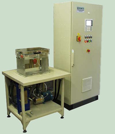
The laboratory's 10 kW processing equipment (source: Keronite.com)
For more information on laboratory equipment such as this or even on industrial scale plasma electrolytic oxidation equipment with capacities up to 3500 litres and 300 kW power, contact Keronite.com.
Structure, Mechanics and Thermo-Mechanical Properties of PEO Coatings
The earliest work of the Gordon Laboratory in the area of plama electrolytic oxidation (PEO) was focussed on evaluating the microstructure, the mechanics, and the thermo-mechanical characterisation of these layers. Led by James Curran, this work established many of the fundamental mechanical properties of the coatings.
The work originally considered only the coatings formed on aluminium, but as the properties of these coatings were evaluated, the work was extended to included evaluation of the coatings on magnesium and titanium, which generally showed similar characteristics. All samples were produced using a range of Keronite™ industrial processing rigs.
The compliance of PEO coatings
One of the most important mechanical characteristics of PEO coatings is their "compliance", or low stiffness. This was first discovered in the Gordon Laboratory. This low stiffness, as in other classical thermally sprayed ceramic coating systems (such as plasma-sprayed YSZ), allows the coatings to experience significant mechanical strain without correspondingly significant stresses.
The elastic modulus of typical Keronite™ PEO coatings on aluminium is just 30-40 GPa, and similar values are observed for the Keronite coatings on magnesium and on titanium.
The highly desriable wear performance of PEO coatings can be partly accounted for by their high hardness (typical hardness values on aluminium are of the order of 1500-2000 HV0.1) , but the compliance also plays an important role in this and must be measured and understood, in order to fully characterise, explain and optimise wear performance.
For further information on the pioneering work on the low stiffness of PEO coatings, see:
Curran, J.A. and Clyne, T.W., "Thermo-physical properties of plasma electrolytic oxide coatings on aluminium", Surface & Coatings Technology, 199, 2-3 (2005): 168-176.
A further consequence of this low stiffness, is that it enables the coatings to withstand significant thermally induced strains without de-bonding or "spallation". This is particularly true of coatings on aluminium and magnesium where there is excellent interfacial adhesion because the coatings are mainly generated by substrate conversion, rather than material deposition.
The porosity of PEO coatings
Another major discovery made in the Gordon Lab during the early days of their research into PEO coating structures, was that even coatings which appear almost fully dense (and were typically described in literature as having porosity of less than 3%), were in fact highly porous on a sub-micron scale. This porosity had been overlooked as it was not visible in typical polished cross-sections.
When precise and accurate density or porosity measurements are made (using techniques such as helium pycnometry, mercury intrusion porosimetry, or BET adsorption) it is found that all coatings contain surface-connected porosity of at least 20%, on a very fine scale (usually extending beyond the measurement capability of such instruments), and that the coatings have correspondingly high specific surface areas (typically of the order of 4 m2 g-1).
The significance of this porosity is that it can be easily infiltrated by lubricants, allowing improved lubricated wear, or that it can be impregnated with polymers or other materials to give good adhesion of top-coats (such as PTFE) in the creation of composite surface layers.
The pore structure is also an essential aspect of the coating formation mechanism, as is being shown by the work of Chris Dunleavy in his investigation into the discharge characteristics observed during PEO processing.
The original work on porosity of PEO coatings has been published as:
Curran, J.A. and Clyne, T.W., "Porosity in plasma electrolytic oxide coatings", Acta Materialia, 54, 7 (2006): 1985-1993.
The thermal conductivity of PEO coatings
A third significant discovery made in the Gordon Laboratory was the low thermal conductivity of PEO coatings. In applying the lab's thermal analysis equipment (which was developed for the analysis of classical thermal barrier coatings such as the plasma-sprayed ceramics) to PEO coatings, it was found that the coatings exhibit similar values of stiffness and thermal conductivity, and can thus deliver similar performance, albeit on substrates which themselves possess greater thermal limitations.
On both aluminium and magnesium, for instance, typical PEO coatings were found to have thermal conductivities of the order of 1 W m-1 K-1. This work was published as:
Tan, J. C., Tsipas, S. A., Golosnoy, I. O., Curran, J. A., Paul, S. and Clyne, T. W., "A steady-state bi-substrate technique for measurement of the thermal conductivity of ceramic coatings", Surface & Coatings Technology, 201, 3-4 (2006): 1414-1420.
Curran, J.A. and Clyne, T.W., "The thermal conductivity of plasma electrolytic oxide coatings on aluminium and magnesium", Surface & Coatings Technology, 199, 2-3 (2005): 177-183.
Further research into more silicon-rich, "mullite-based" PEO coatings on magnesium showed that even lower thermal conductivity values were achievable, together with greater coating thickness, while still retaining the important low-stiffness:
Curran, J. A., Kalkanci, H., Magurova, Yu. and Clyne, T. W., "Mullite-rich plasma electrolytic oxide coatings for thermal barrier applications", Surface & Coatings Technology, 201,21 (2007): 8683-8687.
In all potential thermal barrier applications, the low stiffness of the coatings, discussed earlier, together with the strong adhesion to the substrate, are also important considerations because these reduce the likelihood of coating "spallation" or de-bonding from the substrate metal when exposed to a significant temperature change.
The wear performance of PEO coatings
Much of the historical development of PEO coatings, many of their existing industrial applications, and much of the literature regarding PEO coatings, focusses on their hardness and the resulting wear protection that they can offer to softer substrate metals. On aluminium, for instance, PEO coatings, with typical hardnesses in the range of 1500-2000 HV0.1, offer far greater surface hardness than the substrate (<200 HV) or conventional hard anodising (~500 HV). This is mainly due to the significant volume fractions of crystalline alumina (particularly α-Al2O3) which are generated as a consequence of the localised heating, melting and re-solidification of the growing layer.
The Gordon Laboratory's nanoindentation research has included detailed characterisation of hardness distributions on a wide range of PEO coating types, correlated with microstructures and phase proportions. Of equal importance in delivering good wear performance, however, is the coating compliance (low stiffness) which was first observed in this Lab, as well as the fine-surface connected porosity which offers superior performance under lubricated conditions.
In addition to conventional wear tests, Dr Jeffrey Wheeler has developed micro-scale wear characterisation facilities to characterise wear performance of thin ceramic coatings such as these PEO in a wide range of modes and a under conditions ranging from abrasive, through erosive, to impact wear.
This work is described in Jeffrey Wheeler's thesis, as well as in the following article:
J.M. Wheeler, C.A. Collier, J. Paillard & J.A. Curran, “Evaluation of MicroMechanical Behaviour of Plasma Electrolytic Oxide (PEO) Coatings on Ti-6Al-4V”, Surface & Coatings Technology204 (2010): 3399-3409.
C. Martini, L. Ceschini, F. Tarterini, J.M. Paillard & J.A. Curran, "PEO layers obtained from mixed aluminate-phosphate baths on Ti-6Al-4V: Dry sliding behaviour and influence of a PTFE Topcoat", Wear269 (2010): 747-756.
Discharge characteristics
Through-thickness electrical discharges are fundamental to the PEO process. Discharges are thought to provide a mechanism for exposing the metallic substrate to a source of oxygen from the electrolyte. However, the exact mechanism of breakdown has attracted much debate in the literature, particularly whether breakdown occurs in gas-filled pores or within the solid oxide. It is important to analyse individual discharges in order to understand the process as a whole, and significant efforts have been made in this direction in recent years.
Two methodologies have been developed by the group to isolate individual discharges. The first involves supplying a low power to a sample with a pre-formed coating. The low power means there is only sufficient power for one discharge to initiate at a given time, so monitoring the current flowing in the system allows the current-time profiles of individual discharges to be resolved. The second uses a small area substrate processed in parallel with a larger work piece, in an industrial scale set-up. Samples processed in parallel enable the correct current density to be supplied to the small area sample using an industrial power supply. Reducing the area of the small sample limits the current supplied to it and the probability of having more than one discharge at a time is reduced. The current flowing through the small area sample is monitored along with the applied voltage, allowing the current-time profiles of individual discharges to be resolved.
It must be recognised that discharge events are stochastic in nature and as such large numbers of events should be considered before any conclusions can be made on the current-time profile. This work was pioneered by Chris Dunleavy, and more details can be found in his thesis. Discharge durations were found to be in the range of ~10-100 microseconds, with currents of a few tens of milliamps. This work showed that there is significant similarity of shape between large and small events, in terms of the current–time profiles of individual discharges, see figure 1 (a) and (b). With the exception of the smallest discharge events, the shape is seen to scale with the initiation voltage, Vinit. A rapid rise to the peak current, Ipeak, is followed by a sustained period of steadily decreasing current, before the event terminates as current drops rapidly back to the baseline level. The main variation in the shape of the current-time profile is when the current suddenly shuts off, as can be seen in figure 1 (c), and the shape remains the same throughout processing (i.e. with different thickness coatings), figure 1 (d). This calls into question the hypothesis of different "types" of discharge (as has been suggested in the literature), since different "types" of discharge would probably have distinct current-time profiles.
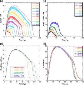
Fig. 1 Plots of averaged current–time relationships for (a) a 42-minute and (b) a 6-minute coating, sorted by event initiation Voltage ,Vinit,for events having the median lifetime tevent. Also shown are (c) average I(t) profiles, sorted by peak current, Ipeak, value, with the central profile corresponding to the median tevent value and the others to events with lifetimes 5, 10 and 15 μs shorter and longer than this, and (d) mean I(t) profiles sorted by Ipeak, for coatings between 12 and 42 min. All profiles correspond to the median tevent at the relevant Ipeak value.
More recently, high speed video imaging has been employed as an effective characterisation method. Electrical monitoring estimated that discharge lifetimes are of the order of a few tens to hundreds of microseconds, whereas estimates based on optical studies were much longer (of the order of milliseconds). High speed imaging, with 180,000 fps, showed that discharges tend to occur in "cascades" at localised positions, which would look like a single long discharge with a longer frame exposure time. High speed video imaging was then synchronised with the electrical monitoring of a small area sample processed in parallel with a bulk sample, as shown in figure 2.
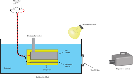
Fig. 2 Schematicset-up of the experimental conditions used for synchronising high speed video with electrical monitoring of individual discharges.
Using a very bright flash lamp, the bubble surrounding an individual discharge can be seen and the dynamics can be assessed, showing that the pressure and temperature within the bubble is relatively low (1-2 atm and ~100 °C). Using the electrical data, the energy input can be estimated and an energy audit of the processes occurring during an individual discharge can be performed. This showed that the major energy absorption mechanism is the transient vaporisation of electrolyte surrounding a discharge site, followed by heating of the surrounding electrolyte.
Publications based on this research
The work that has been briefly outlined in the previous pages is described in fuller detail in the following publications:
S. C. Troughton, A. Nominé, A. V. Nominé, G. Henrion, T. W. Clyne "Synchronised electrical monitoring and high speed video of bubble growth associated with individual discharges during plasma electrolytic oxidation." Applied Surface Science, 359 (2015): 405-411
A. Nominé, S. C. Troughton, A. V. Nominé, G. Henrion, T. W. Clyne "High Speed Video Evidence for Localised Discharge Cascades during Plasma Electrolytic Oxidation." Surface and Coatings Technology, 269(2015): 125-130
J. Dean, T. Gu, T. W. Clyne "Evaluation of residual stress levels in plasma electrolytic oxidation coatings using a curvature method" Surface and Coatings Technology, 269(2015): 47-53
C. S. Dunleavy, J. A. Curran, T. W. Clyne "Time dependent statistics of plasma discharge parameters during bulk AC plasma electrolytic oxidation of aluminium" Applied Surface Science, 268 (2013): 397-409
L. K. Mirelman, J. A. Curran, T. W. ClyneThe Production of Anatase-rich Photoactive Coatings by Plasma Electrolytic Oxidation
Surface and Coatings Technology, 207 (2012):66-71
C. S. Dunleavy, J. A. Curran, T. W. Clyne "Self-similar scaling of discharge events through PEO coatings on aluminium" Surface and Coatings Technology, 206, 6 (2011): 1051-1061
C. Martini, L. Ceschini, F. Tarterini, J.M. Paillard & J.A. Curran, "PEO layers obtained from mixed aluminate-phosphate baths on Ti-6Al-4V: Dry sliding behaviour and influence of a PTFE Topcoat", Wear269 (2010): 747-756.
J.M. Wheeler, C.A. Collier, J. Paillard & J.A. Curran, “Evaluation of MicroMechanical Behaviour of Plasma Electrolytic Oxide (PEO) Coatings on Ti-6Al-4V”, Surface & Coatings Technology204 (2010): 3399-3409.
C. S. Dunleavy, J. A. Curran, T. W. Clyne "Plasma electrolytic oxidation of aluminium networks to form a metal-cored ceramic composite hybrid material" Composites Science and Technology, 71, 6 (2011): 908-915
C. S. Dunleavy, I. O. Golosnoy, J. A. Curran, T. W. Clyne "Characterisation of discharge events during plasma electrolytic oxidation" Surface and Coatings Technology, 203, 22 (2009): 3410-3419
Curran, J. A., Kalkanci, H., Magurova, Yu. and Clyne, T. W., "Mullite-rich plasma electrolytic oxide coatings for thermal barrier applications", Surface & Coatings Technology, 201,21 (2007): 8683-8687.
Curran, J.A. and Clyne, T.W., "Porosity in plasma electrolytic oxide coatings", Acta Materialia, 54, 7 (2006): 1985-1993.
Tan, J. C., Tsipas, S. A., Golosnoy, I. O., Curran, J. A., Paul, S. and Clyne, T. W., "A steady-state bi-substrate technique for measurement of the thermal conductivity of ceramic coatings", Surface & Coatings Technology, 201, 3-4 (2006): 1414-1420.
Curran, J.A. and Clyne, T.W., "The thermal conductivity of plasma electrolytic oxide coatings on aluminium and magnesium", Surface & Coatings Technology, 199, 2-3 (2005): 177-183.
Curran, J.A. and Clyne, T.W., "Thermo-physical properties of plasma electrolytic oxide coatings on aluminium", Surface & Coatings Technology, 199, 2-3 (2005): 168-176.
Further details are also included in the PhD theses of James Curran, Katerina Plati, Shiladitya Paul, Amaia Cipitria, Hande Kalkanci, Jeffrey Wheeler, Julien Paillard, and Chris Dunleavy.